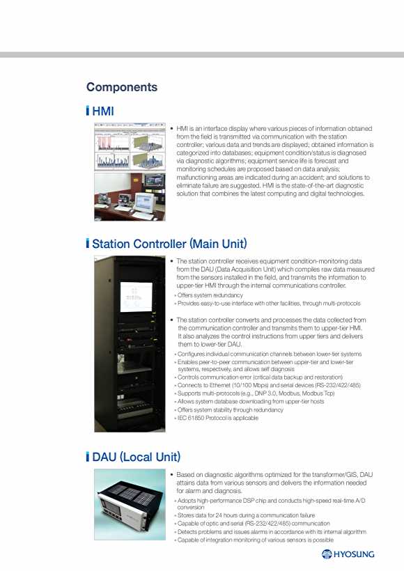

Components HMI •HMIisaninterfacedisplaywherevariouspiecesofinformationobtained from the field is transmitted via communication with the station controller; various data and trends are displayed; obtained information is categorized into databases; equipment condition/status is diagnosed via diagnostic algorithms; equipment service life is forecast and monitoring schedules are proposed based on data analysis; malfunctioning areas are indicated during an accident; and solutions to eliminate failure are suggested. HMI is the state-of-the-art diagnostic solution that combines the latest computing and digital technologies. Station Controller (Main Unit) •Thestationcontrollerreceivesequipmentcondition-monitoringdatafrom the DAU (Data Acquisition Unit) which compiles raw data measured from the sensors installed in the field, and transmits the information to upper-tier HMI through the internal communications controller. » Offers system redundancy » Provides easy-to-use interface with other facilities, through multi-protocols •Thestationcontrollerconvertsandprocessesthedatacollectedfrom the communication controller and transmits them to upper-tier HMI. It also analyzes the control instructions from upper tiers and delivers them to lower-tier DAU. » Configures individual communication channels between lower-tier systems » Enables peer-to-peer communication between upper-tier and lower-tier systems, respectively, and allows self diagnosis » Controls communication error (critical data backup and restoration) » Connects to Ethernet (10/100 Mbps) and serial devices (RS-232/422/485) » Supports multi-protocols (e.g., DNP 3.0, Modbus, Modbus Tcp) » Allows system database downloading from upper-tier hosts » Offers system stability through redundancy » IEC 61850 Protocol is applicable ( ) DAU Local Unit •Basedondiagnosticalgorithmsoptimizedforthetransformer/GIS,DAU attains data from various sensors and delivers the information needed for alarm and diagnosis. » Adopts high-performance DSP chip and conducts high-speed real-time A/D conversion » Stores data for 24 hours during a communication failure » Capable of optic and serial (RS-232/422/485) communication » Detects problems and issues alarms in accordance with its internal algorithm » Capable of integration monitoring of various sensors is possible
Monitoring and Diagnosis Items Partial Discharge •Throughtheanalyzerinstalledinthefield,UHFsignal,generated when partial discharge occurs in GIS, is captured, and the PD magnitude (pC), cause, location, tendency, and risk are analyzed to provide reasonable data on the operating condition. •Monitoringtimeandservicelifecanbeforecast,andawarning(message) is issued and monitoring instructions are provided when the set limits are reached. Φ Φ •FeaturessuchasPRPD( -q-n), PRPS ( -q-t), and noise masking are offered selectively. •Externalnoisesensorfornoiseelimination(Optional) Lightning Arrester Degradation Monitoring •Thetotalleakagecurrentand3rdharmonicleakagecurrentofthe lightning arrester are monitored constantly, and at the same time the trend can be identified. •Whenthethresholdvaluearereached,awarning(message)is issued, and the information on monitoring time and remaining service life is provided. SF Gas Density 6 6 •Usinggasdensitysensors,thepressureofSF gas (GIS insulation medium) is monitored, and a sensor is mounted in each gas section to monitor the gas-tightness. •Duringinternalflashover,thoughveryrare,theinstantaneousriseinpressure is identified to locate where failure has occurred and to allow prompt maintenance. Operating Characteristics of CB The measurement of the current and operating time of trip coil, the current and operating time of close coil, the operating time of mechanical aux. contact and CB traveling curve are measured to find if there is any problem with the control circuit, control pressure or CB, if there is any delayed operation in the hook/pilot/main valve, any problems with CB due to abrasion/deformation. I 08 09 HiCMS Hyosung intelligent Condition Monitoring System