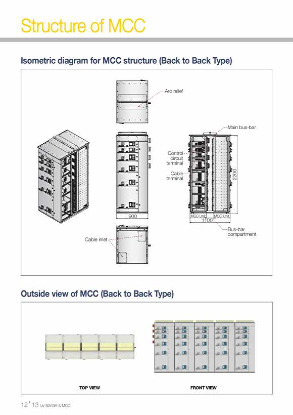

Structure of MCC Isometric diagram for MCC structure (Back to Back Type) Arc relief Main bus-bar Control circuit terminal 0 Cable 0 2 terminal 2 900 MCC Unit MCC Unit 1100 Bus-bar compartment Cable inlet Outside view of MCC (Back to Back Type) TOP VIEW FRONT VIEW I 12 13 LV SWGR & MCC
Features of MCC Horizontal bus-bar Vertical bus-bar Horizontal Main bus-bars are mainly installed at rear middle Vertical busbars are installed at rear side and segregated with partofcubicleinverticalconfigurationbutitisalsopossibletometallic plates between units to provide protection against arc installedthematrearupperpartinhorizontalconfiguration. conditions and automatic safety shutters are installed in the Horizontal Main bus-bars are separately installed in under primary plug connections to cover busbar connections during bus-bar compartment with metallic segregation plates. withdrawal of MCC units for the safety of users. Especially,verticalbus-barsarecompletely embedded under polyamide synthetic insulation support with consideration of higher safety aspects.and is designed/manufactured to withstand Size of Horizontal bus-bar thermal/mechanical impacts caused by accidental current. Current rating Bus-bar size 630 10t x 50mm x 1sheet 800 10t x 50mm x 1sheet 1000 10t x 60mm x 1sheet 1250 10t x 75mm x 1sheet 1600 10t x 100mm x 1sheet 2000 10t x 75mm x 2sheets 2500 10t x 100mm x 2sheets Size of vertical bus-bar 3200 10t x 125mm x 2sheets Short circuit Current Bus-bar size current rating 4000 10t x 125mm x 3sheets 65kA 1000 U TYPE 6/10t x 42mm x 37mm 5000 10t x 125mm x 4sheets ≤65kA 630 L TYPE 6/6t x 42mm x 37mm Horizontal and vertical bus-bar