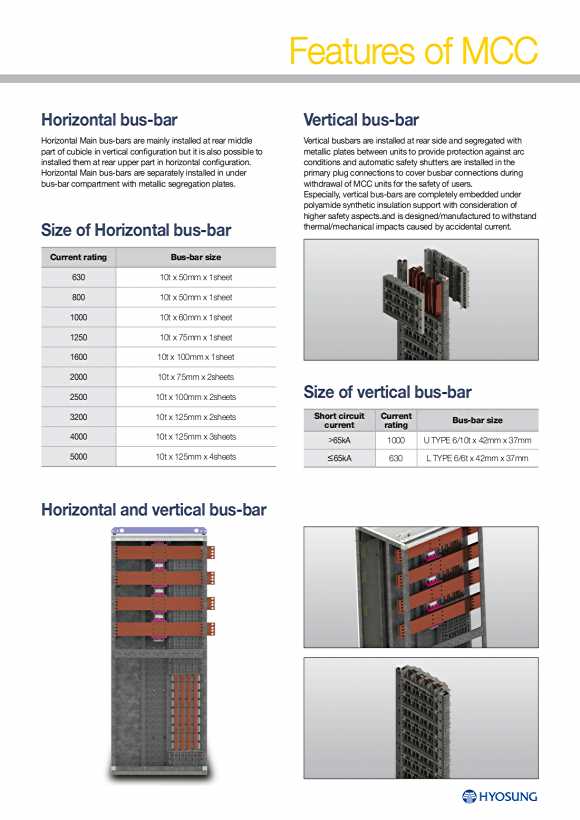

Features of MCC Horizontal bus-bar Vertical bus-bar Horizontal Main bus-bars are mainly installed at rear middle Vertical busbars are installed at rear side and segregated with partofcubicleinverticalconfigurationbutitisalsopossibletometallic plates between units to provide protection against arc installedthematrearupperpartinhorizontalconfiguration. conditions and automatic safety shutters are installed in the Horizontal Main bus-bars are separately installed in under primary plug connections to cover busbar connections during bus-bar compartment with metallic segregation plates. withdrawal of MCC units for the safety of users. Especially,verticalbus-barsarecompletely embedded under polyamide synthetic insulation support with consideration of higher safety aspects.and is designed/manufactured to withstand Size of Horizontal bus-bar thermal/mechanical impacts caused by accidental current. Current rating Bus-bar size 630 10t x 50mm x 1sheet 800 10t x 50mm x 1sheet 1000 10t x 60mm x 1sheet 1250 10t x 75mm x 1sheet 1600 10t x 100mm x 1sheet 2000 10t x 75mm x 2sheets 2500 10t x 100mm x 2sheets Size of vertical bus-bar 3200 10t x 125mm x 2sheets Short circuit Current Bus-bar size current rating 4000 10t x 125mm x 3sheets 65kA 1000 U TYPE 6/10t x 42mm x 37mm 5000 10t x 125mm x 4sheets ≤65kA 630 L TYPE 6/6t x 42mm x 37mm Horizontal and vertical bus-bar
Unit Arrangement Unit arrangement Service position ▼ Test position ▼ If unit locking devices show Lock positions, the draw-out Circuit control draw-out connectors are only connected for testing connectors of primary and secondary plugs of main circuit and units and the user may check the output signals of all the control control circuits are connected with each circuit. If a unit is not circuits. adequately inserted, the locker is not completely fastened. ③ ③ ④ ④ ① ① ⑦ ⑦ ② ⑤ ② ⑤ ⑧ ⑧ ⑥ ⑥ Withdrawn position ▶ ③ ④ All the draw-out connectors of primary and secondary plugs of ① ⑦ main circuit and control circuits are disconnected and the units may be completely separated from cubicles. ② ⑤ Withdrawable modules are applied with special sliding type terminal blocks for control circuits’ connections in place of conventional plug & socket type terminals blocks to provide easy maintenance and less wiring works for connection between control ⑧ terminal blocks and devices. ⑥ ① Vertical bus-bar ④ Secondary service plug of main circuit ⑦ Form 4b box ② Primary plug of main circuit ⑤ Fixed plug for control circuit ⑧ Draw-out unit ③ Secondary fixed plug of main circuit ⑥ Service plug for control circuit Arrangement of unit devices ❸ ❻ ❹ ❶ ❺ ❶ Base plate of unit ❷ Position locking device ❸ Primary plug of main circuit ❷ ❹ Secondary plug of main circuit ❺ Control circuit plug ❻ Limit switch I 14 15 LV SWGR & MCC