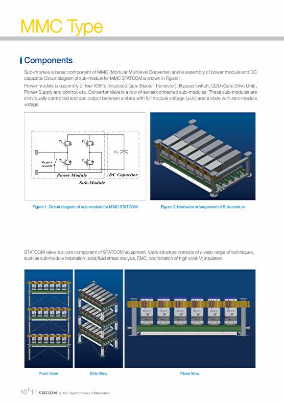

MMC Type Components Sub-module is basic component of MMC (Modular Multilevel Converter) and is assembly of power module and DC capacitor. Circuit diagram of sub-module for MMC STATCOM is shown in Figure 1. Power module is assembly of four IGBTs (Insulated Gate Bipolar Transistor), Bypass switch, GDU (Gate Drive Unit), Power Supply and control, etc. Converter Valve is a row of series connected sub-modules. These sub-modules are individually controlled and can output between a state with full module voltage (��Uc) and a state with zero module voltage. T1 T3 UC T2 T4 Byp ass Switch Power Module D C Cap acitor Sub-Module Figure 1. Circuit diagram of sub-module for MMC STATCOM Figure 2. Hardware arrangement of Sub-module STATCOM valve is a core component of STATCOM equipment. Valve structure consists of a wide range of techniques, such as sub-module installation, solid/fluid stress analysis, EMC, coordination of high volt(HV) insulation. Front View Side View Plane View I 10 11 STATCOM STATic Synchronous COMpensator
MMC Type Operation ? MMC Technologies IGBT Full Bridge DC Capacitor T1 T3 Uc T2 T4 Bypass Switch Power Module Converter 1 Phase Converter Full-Bridge Transformer Submodule 154kV:21kV Y Phase 3�� Reactor GIS Harmonic Star-point Filter Reactor ? Multi Level Output Each power module gets its power from the DC 42 Level Output Voltage capacitor in its own module. Power is used for operating the SM controller and Evalv 80 GDU for IGBT firing. Sub-module Controller has 60 the following functions : 40 ? Receive trigger signal from the Phase Controller 20 ? Monitor the Sub-module condition and transmit 0 the status of sub-module to Phase Controller -20 ? Generate firing signal for IGBT��s and Bypass -40 switch (to remove failed sub-module in -60 the electrical circuit of MMC) -80 ? Measure the capacitor voltage of the sub-module x 3.2000 3.2025 3.2050 3.2075 3.2100 3.2125 3.2150 3.2175 3.2200