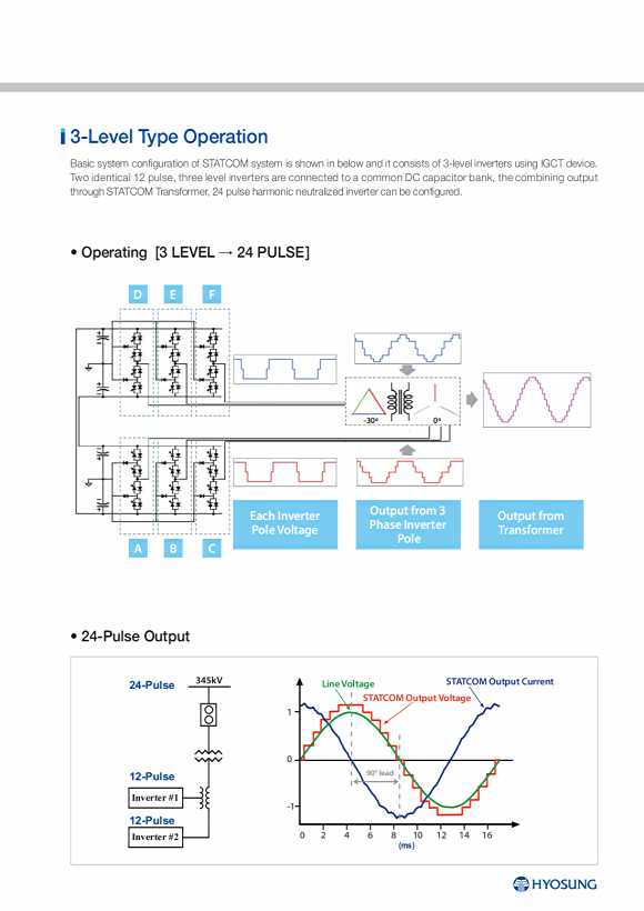

3-Level Type Operation Basic system configuration of STATCOM system is shown in below and it consists of 3-level inverters using IGCT device. Two identical 12 pulse, three level inverters are connected to a common DC capacitor bank, the combining output through STATCOM Transformer, 24 pulse harmonic neutralized inverter can be configured. ? Operating [3 LEVEL �� 24 PULSE] D E F -30�� 0�� Each Inverter Output from 3 Output from Phase Inverter Pole Voltage Transformer Pole A B C ? 24-Pulse Output 24-Pulse 345kV Line Voltage STATCOM Output Current STATCOM Output Voltage 1 0 12-Pulse 90�� lead Inverter #1 -1 12-Pulse Inverter #2 0 2 4 6 8 10 12 14 16 (ms)
MMC Type Components Sub-module is basic component of MMC (Modular Multilevel Converter) and is assembly of power module and DC capacitor. Circuit diagram of sub-module for MMC STATCOM is shown in Figure 1. Power module is assembly of four IGBTs (Insulated Gate Bipolar Transistor), Bypass switch, GDU (Gate Drive Unit), Power Supply and control, etc. Converter Valve is a row of series connected sub-modules. These sub-modules are individually controlled and can output between a state with full module voltage (��Uc) and a state with zero module voltage. T1 T3 UC T2 T4 Byp ass Switch Power Module D C Cap acitor Sub-Module Figure 1. Circuit diagram of sub-module for MMC STATCOM Figure 2. Hardware arrangement of Sub-module STATCOM valve is a core component of STATCOM equipment. Valve structure consists of a wide range of techniques, such as sub-module installation, solid/fluid stress analysis, EMC, coordination of high volt(HV) insulation. Front View Side View Plane View I 10 11 STATCOM STATic Synchronous COMpensator